Monday, December 28, 2009

Bearing shaft removal from Rollerhead/Carriage

I've been informed that more pictures would be nice. OK, here you go!

You need a 1/8" Allen Wrench and a 1/2" Socket (deep version) with ratchet.

Two of the shafts are concentric and are held in place by set screws. Use the Allen wrench to move those two set screws.

I will replace them with brass versions - part number 92991A533 at McMaster.

Now remove the 4 x 1/2" nuts and lock washers from each shaft.

Take a bolt or whatever else you like to use as a large punch and then tap the shafts out of the Rollerhead.


Now to remove the bearings from each shaft.


Unscrew the keeper nut a bit so that you have something other than the shaft to tap against.


Take the 1/2" socket and fit it onto the head of the shaft.


Turn it over and place the socket on a solid surface.


Now tap on the shaft and push it out of the bearing and into the socket.


It shouldn't take much at all.


Free as a bird.


Everything ready to be cleaned up.

Sunday, December 27, 2009

Off Topic? - Craigslist

I just saw this (no pun intended) on Craigslist:

Dec 27 - DeWalt Radial Arm Saw - $200 - (redwood city)

DeWalt Model 235 Radial Arm Saw w SN 61111183. Buyer must pick up and haul. Must sell this year. $200 or Best Offer. Call Xxxx at 408-XXX-XXXX.


No picture, of course. The thing is only the 925 came with a frame 235 motor so what we are looking at is an ad for a Model 925. "Must sell this year. $200 or Best Offer." sounds a lot like $25 bucks to me on Thursday the 30th, what do you think?

Who knows what condition it is in? Not the seller, apparently. Is it the Deluxe Edition or just a regular old 925? Hard to say... odds are it is a regular 925 in poor condition but you know I'm going to have to find out one way or another.

I'll take a camera with me if I do and report back here.

I have to shake my head. If the ad said "1959 DeWalt Model 925" and had a decent image he probably would have already gotten about 4 phone calls from my local DeWalt RAS collecting competition.

Update - I called the guy and will see the saw tomorrow (12/30/09). Turns out he bought it as part of a package deal from a guy who bought it as part of a package deal from an estate sale. I doubt he has ever turned it on.

Update #2 - OK, I'm a jerk. It turns out it was a 925DLX in excellent condition that came with the ultra cool 1961 accessory box containing, among other things, a shaper guard in brand new condition. Yes, I totally bought it.

Day 7 - Yoke and Carriage Separation

Now it's time to separate the carriage from the yoke. First, locate the King Bolt Set Screw. Get a good quality screwdriver and unscrew it carefully. This is another one of those parts that is hard to come by.

Keep in mind the screw is hardened steel and the yoke is aluminum. You DO NOT want to be in a position where you are needing to drill out the remainder of a stuck set screw. If it doesn't unscrew steadily soak that bastard in PB Blaster or Kroil for as long as possible, working the screw in and out.


Here's what it looks like (needs to be cleaned up).


Next, we'll remove the King Bolt. A drag link socket comes in handy for this sort of thing.


Before removing it, note its exact orientation to the set screw hole. This will make it easier to position properly when you put it back together.


Mine came out easily, revealing a shim washer between the yoke clamp and the yoke. You can see the grooves in the king bolt that the set screw fits into.


The two parts separated. On the left hand side of the image you can see the Index Pin peeking out. Remove its handle and it should just push through. In my case it was too rusted.


I had to visit the wire wheel with the pin still in the carriage, pull it out as far as possible and then polish off the rust near the handle. It was then able to come through. The spring is still in the carriage, apparently.


Similar deal when removing the Release Pin. Loosen the bevel clamp and then pull the hub out. Back to the wire wheel to get the rust off of the top of the Release Pin and then out it came.

Saturday, December 26, 2009

Quick Motor Update

I cut away some of the material I suspected was causing the noise and it is better but still not "right". It's good enough for now, though. One sound per rotation has me scratching my head as the rotor assembly prides itself on being symmetrical. The next time I pull it apart I will mark the arbor on the spot where the noise occurs and take a look with the calipers.

Next up... separating roller carriage from the yoke and disassembling both.

Tuesday, December 22, 2009

Snag #1

Houston, we have a problem.

Something I did not check when I went to pick up the saw. The miter adjustment screws.

Oops.


They are rusted into the cast iron. Totally rusted. Stuck. Frozen. Fused.

I tried banging on them, torching them with propane and MAPP. PB Blaster for days. Impact Driver (broke two bits).

Bummer.

So I hooked up with my main man in NY, Jude (Beta Zeta). This is an enigmatic figure who apparently collects saws from the NY area and parts them out. He is very active.

A couple of emails later I secured a 925 arm with screws in good working order for $20 bucks. Another $30 to ship it but why mess around? God willing this is the last hurdle.

Day 6 - A little more motor

I got my new motor bearings from Accurate and pressed them onto the rotor. To press them on I use a long socket that fits the bearing races. Make sure it is long enough to press the bearing on and not get stuck on the arbor, many aren't.

Then I used the hair dryer to warm the front bell for 60 seconds and fitted the front bearing into the bell. I pushed it in about 3/4 of the way in by hand. Good enough. Now take one of the tie rods that hold the motor together and fish it through the front retainer ring and through the bell. Using your fingers to hold the rear retainer in place and then thread the tie rod into one of the retainer's threaded holes. It's a pain. Once you do this you have a way to position and hold the damned retainer so you can thread the real screws through the front retainer and into the rear without it constantly shifting around.

Once you have the other three threaded, remove the tie rod and thread the last screw on. Them , this is important, tighten them all evenly, 1/2 turn at a time to pull the bearing the rest of the way into the bell but do not fully tighten them.

I could have pressed them back together but I chose this method because I wanted to be able to "fine tune" the tension when messing with the motor.

Now gently push the rotor into the motor housing so as not to scratch the stator. Fit the rear bearing into the rear housing after warming it with a hair dryer for 60 seconds. Now fit it in. You'll probably need to tap the front arbor to get the rear bearing into place. Take care to do it straight.

Now thread the tie rods through the motor housing into their nuts and tighten everything up a bit. Not all the way, just so the rotor can spin without scraping anything.

Plug in the motor and flip the switch. It runs! Yay. The relay works great. The motor spins strongly but I hear lots of oscillations. If it's not spinning smoothly turn the motor off immediately, of course!

Now tighten the tie rods and see what happens. Shift the position of the front bell if needed to minimize vibrations. Also finish tightening the screws on the front retaining ring.

In a perfect world it would be absolutely silent except for a slight hum and vibration. Listen to the motor. Envision a reason for each noise that you are hearing.

In my case my spider sense was tingling. I turned the motor off and felt the arbor. A bit warm. Hmmm. I spun the arbor by hand and hear a slight "tiff" tiff" tiff" sound, one for each rotation of the arbor (and different sounding depending on whether you are spinning clockwise or counter clockwise). Hmmm. And the motor housing is now warm to the touch. Hmmm.

Remove the tie rods, tap the rear arbor and remove the rotor again. This time the bearing stayed in the housing again. Fair enough, I left it there.

I took a look and saw something slightly dismaying - there is a piece of winding insulation cloth sticking out just enough to brush against the rotor, probably the brake unit, as it spins. Take a look at this view down the barrel and look at the top part of the hole. See it?


That is enough to really cause a major problem. I'll have to think about this a bit. This is Snag #2, actually. Read about Snag #1 here.

Friday, December 18, 2009

Couldn't leave well enough alone

In the interests of keeping this all honest I'll tell you about a little blunder (or two, or three...).

Today I had some cycles and decided to install the capacitor I ordered on Day 1. That was easy enough. I used a soldering iron to remove the old capacitor and crimped some female blade connectors onto the wires and plugged it in. Easy as pie.

Then I decided to mess with the relay...

Long story short I cracked the little ceramic head the pushes the points open and watched it fall apart. Oops! Hmmm. I decided to use a piece of a ballpoint pen as a replacement for the old ceramic piece. Same length and basic size, very hard plastic. I filled it with epoxy, let it dry, drilled a small hole in it and glued it into place.


It works great! You may also note my mods to the relay. On the left hand side of the image you can see where I bent the lever so that it doesn't strike the bracket any more. I also bent the other ends so that they connect more fully with the magnet. Why? Because I wanted to :-) The working theory being that the relay should be firmly open or closed at all times. Who knows, I may have just defeated an intentional design decision by the open frame relay people but I'll find out soon enough.

I've also been struggling with the motor, I pressed the new bearings on, went to put it back in the motor and realized I had left the retaining ring off. Press it apart, add the ring, press it back together, and then realize that I had created a major burr on the arbor (?). WTF? The thing was flawless 20 minutes ago.


Anyway, I'll need to disassemble it again and file that burr off so the arbor spacer with fit into place. All this to test the motor so I can pull it apart again....

Haste makes waste, so true... but less all of this, initial feel of the rotor in the new bearings is awesome. I put it together (without the fan) and fired it up. Bam! Nice and powerful! Not perfect or even OK, though. More about that on Day 6.

This motor design is really something else. I don't know who they had working for them but they were artists. This thing is all about subtlety and flexibility. The fact that a ham handed guy like me can mess with this thing 49 years later and get it working so smoothly is really a testament to their efforts.

Wednesday, December 16, 2009

Cosmetics and Costs

Here comes the costliest and most time consuming aspect of restoration by far - cosmetic work.
  • Stripping
  • Painting/Powder Coating
  • Cleaning/Shining/Polishing metal parts
  • The Column
  • Knobs
  • Badges

I use the word "cosmetic" because, with the exception of cleaning some parts, none of this will affect the function of the saw.

Bead blasting and professional painting of the metal parts will run you roughly $250.00.

Powder coating is another $50 on top of that (and you can't powder coat the motor because the winding insulation will melt at 400° unless you have special insulation applied).

Having the column polished and plated is roughly $100.00

To re-create badges you need some illustrator skills, a scanner, and manufacturer of badges that still can do etching.

I have the skills for the former and found a place somewhat local to me to do the latter:

Melrose Nameplate and Label Company.

I will post the costs once I get an estimate. I suspect it will be pricey ;-)

For this saw I intend to re-create the smaller arm badge and create a water slide decal for the larger arm badge.

My current thinking is to paint or powder coat the 925 black, keep the red ball knobs, and replace the mushroom knobs with Stainless Steel flat versions from McMaster. $5.83


What does this really mean? In short, don't bother restoring these smaller saws for profit.

Initial Cost - $0.00
Capacitor - $10.00
Strip and Paint - $300.00
Column - $100.00
Knobs - $12.00
Bearings - $50.00
New Table - $40.00
New Hardware - $20.00
New Cord - $20.00

So we're looking at $552.00 to restore a FREE saw that no one will want to buy for more than $300 if you're patient and lucky. That's the downside.

I imagine you could have someone blast the parts for ~$100 and paint them yourself to save ~$200.

You could polish the column yourself (if you had a fatty wire wheel setup) but that is a lot of work (really) to save yourself another $100 but you still probably couldn't recoup your costs.

The upside is that this saw will last forever so it makes one heck of a gift for a young woodworker, school, or church.

If you are a woodworker you just spent $552.00 on a saw that can't be bought at any price and will last the rest of your woodworking life (and well into your children's and grand children's, should you be so lucky).

The 925 is a 1 horsepower saw. It would take same cost to restore a 1.6 - 5HP saw which a professional who knows that value of a RAS is would happily pay $600-$3500.00 for. The only modern RAS's available worth buying are the Delta or an OSC (Original Saw Company) which will run you $1600-$6000 and not be in the same class as a well restored and calibrated saw from 1953-1971.

To give you an example, I purchased a ~1970 DeWalt B&D Model 3526 which is a 3HP 3 Phase saw with a 46" arm that can perform 24" cross cuts for $200.00. I spent $300.00 to have the motor shop put bearings on it and balance the rotor. And another $185.00 on a VFD (1 to 3 phase converter controller). This saw blows the OSC model (costing $6000.00) out of the water! It will also allow me to sell my 2HP Craftsman Table Saw which I have never loved (I won't tell you what I paid for it but it was more than $500.00).

So $685.00 for a better than $6000.00 model. Not bad.

Time to get organized

I am now at the point where I am waiting for the motor bearings to arrive and this saw is sitting here staring at me.

It is very difficult but now is the time to STOP taking stuff apart (like Day 5) and get organized. Once you start unscrewing, un-bolting, etc you are going to have a lot of small parts, many similar in size and shape, that love to simply disappear.

First you need a box/bin, whatever vessel that is big enough to hold all these small parts. I use these clear Rubbermaid storage bins:


Next get an assortment of plastic zip-lock style bags. Snack, Sandwich, and Freezer sizes.

Last, a permanent "Sharpie" type marker.

As you go, put the various parts and pieces into the right sized bag and label them. Smaller bags can be added to larger bags, etc and thrown into the bin along with the larger parts. The next time you need that particular jam nut you should be able to find it easily.

Day 5 - Removing the arm and some poking around


If you look at the base of the elevating handle you can see a tapered pin inserted into it and through the elevating mechanism

After soaking things with WD40, PB Blaster or Kroil, take a punch and a ball peen hammer, tap that guy out of there, and remove the handle.


Here we have a view of the top of the Thrust Cap. I know from experience that those two screws will not come out of there without some serious torque. No one knows why because there just isn't that much surface area involved but it's just one of those things!


Out comes the impact wrench! A Hand Impact Driver will work just as well.


They popped right out. Take this opportunity to hose the top of the column down with some WD 40 and make sure you can rotate the arm freely.


Here you can see the two shim washers. One was on top of the Thrust Cap and one below.


Here you can see the clamp handle rod, the 3/8-16 Left Hand Hex Nut, and the 1/4" x 1" cotter pin. Take your punch and tap the cotter pin out. Then remove the hex nut and take the Clamp Handle Rod out of the arm, bearing in mind that it is a left hand threaded nut.


This one's got a lot of surface rust (but it will clean right up!).

After the arm can move freely on the column support it firmly and lift it as evenly as possible off of the top of the column. It is precision machined so if you keep the pressure even it should not be a problem.


Here is the top of the column sans arm.


Here is the bottom view of the vanquished arm and wiring.


Here is the "before" of the elevating handle and knob.


Here is the "after", meaning an initial trip to the wire wheel and buffer (more on those later). I still have a lot to do on the knob but it's a good start.

Tuesday, December 15, 2009

Day 4 - Separate Motor from Yoke/Roller Carriage

Welcome to Day 4.


First we need to remove the "Safety Plate". You just need a decent Philips Head Screwdriver to remove the two screws (8-32 1/4").


This reveals the "Trunnion Bushing" and the "Support Screw". The bushing is held in place by 3 set screws 2 x 10-24 1-1/4" cup point set screws and 1 x 10-24 1" of the same (on the bottom). They have jam nuts on them as well (3/8" width).


Now to the front. Same deal. Remove the screws and the "Bevel Pointer".


This reveals the 3 Socket Head Cap Screws. 2 x 5/16-18 1-1/4" and 1 x 3/8-16 1".

In this picture you can see that I have set up some blocks under the motor. Lower the arm and motor onto the blocks to it will have a place to rest when we free the motor from the yoke.

Back to the Trunnion side use a 3/8" hex wrench to remove the Support Screw. This one came out nice and smooth :-)


Use a 3/8" box wrench to loosen the jam nuts.


Use a 3/32" Allen Wrench to back out the top set screws by 1/4" or so to free the Trunnion Bushing.


Remove the bushing.


Now use Hex wrenches to remove the 5/16" and 3/8" Cap Screws and washers. Again, these came out smoothly.

Raise the arm and yoke to leave the motor resting on the blocks. Pull the yoke forward and out of the ways. Don't force it if it doesn't want to come out (more on that later).


Freedom! Time to get organized and do a little cleaning.

Day 5

Monday, December 14, 2009

Day 3 - More Motor

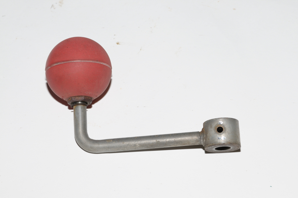
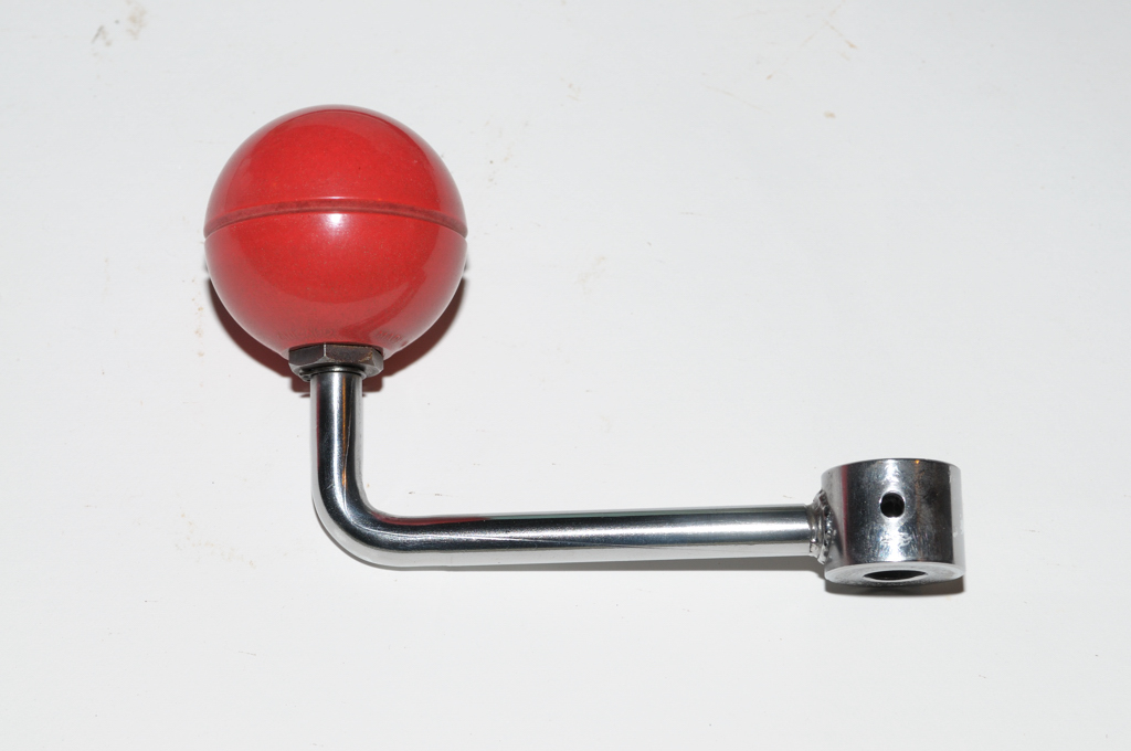
It turns out I needed a little more force.

Step 14 - I had a few minutes so I decided to try the puller again.


It worked!

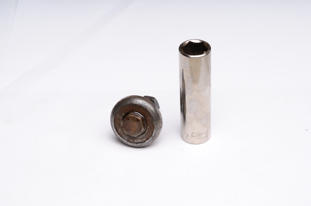
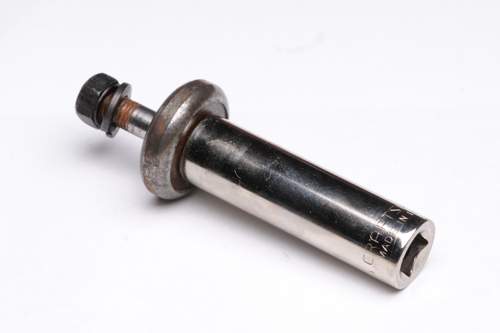
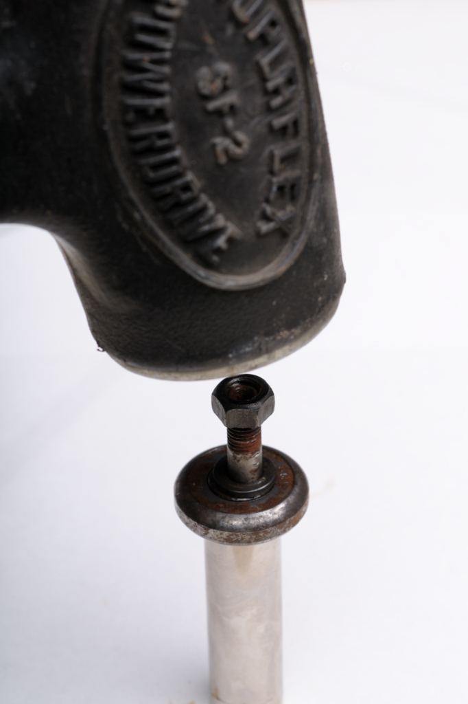
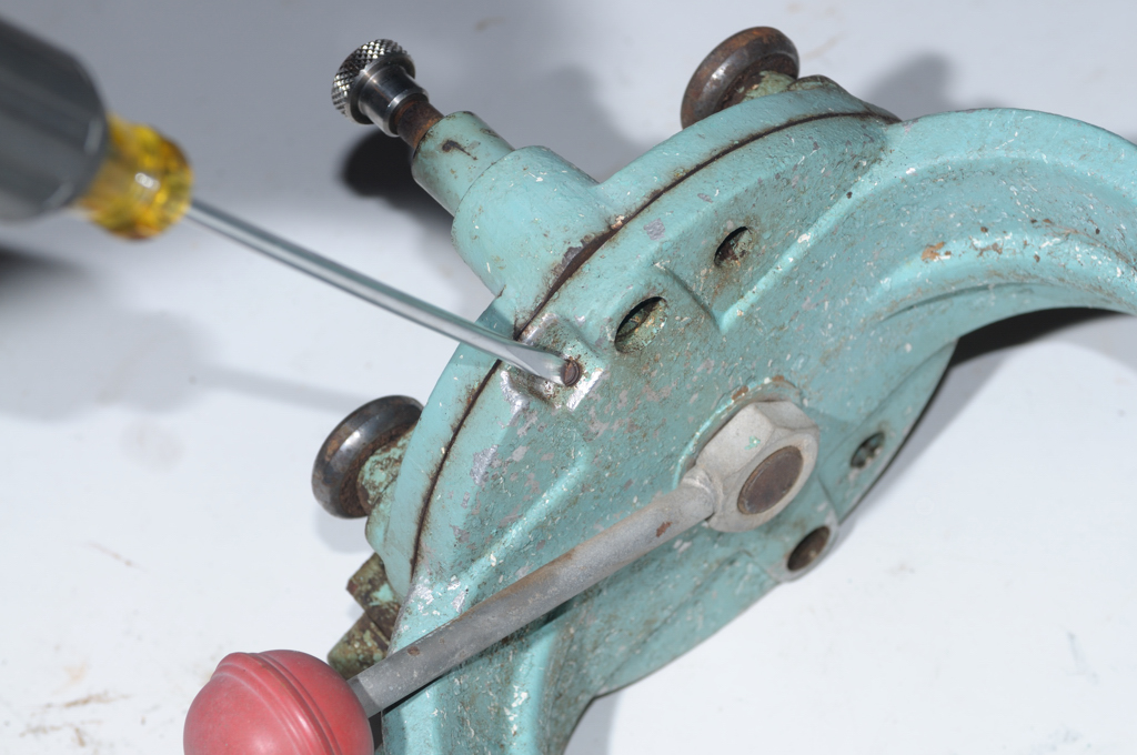
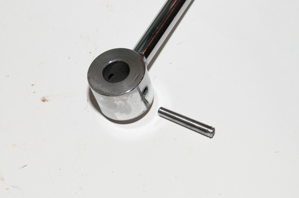
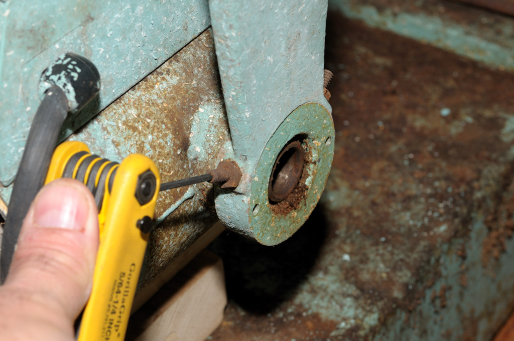
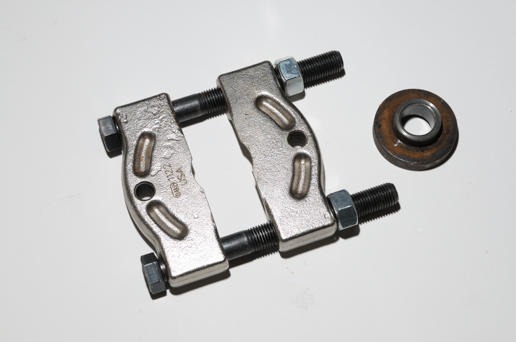
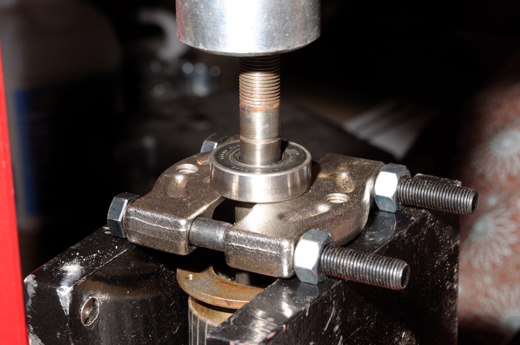
Here's a new ingredient (tool) called a bearing splitter. Quite useful.


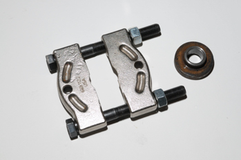
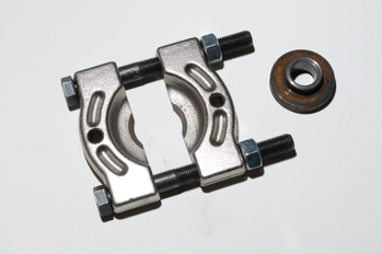
It is an adjustable collar that lets you get pressure right where you need it - on the races of the bearing or whatever else you are pulling.

The 
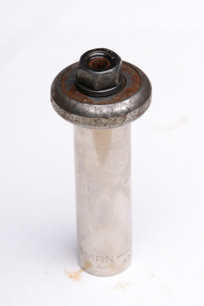
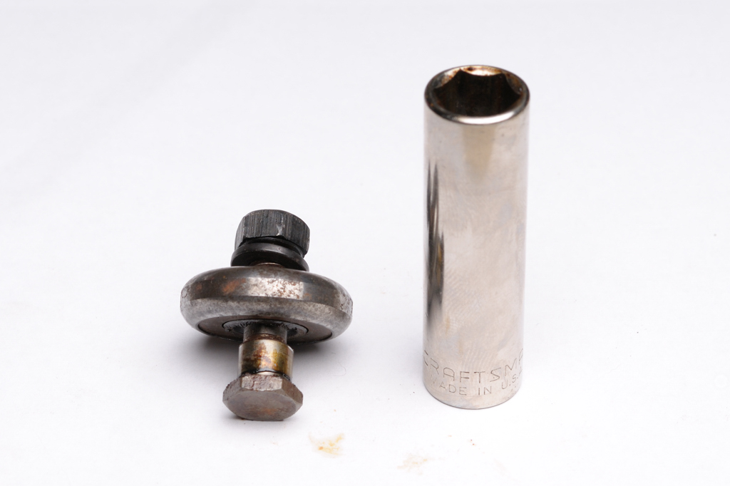
OTC 1122 Splitter - $34.99 I use is made to be used with 2 or 3 arm pullers which could do the work of my press (with a little caution) for pulling stuff. Pressing bearings back on is a different story. OTC makes good ones. No, I don't get a kickback from anyone.

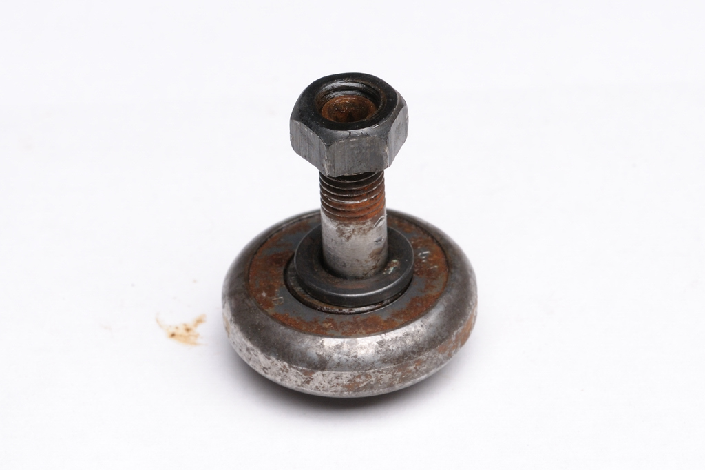
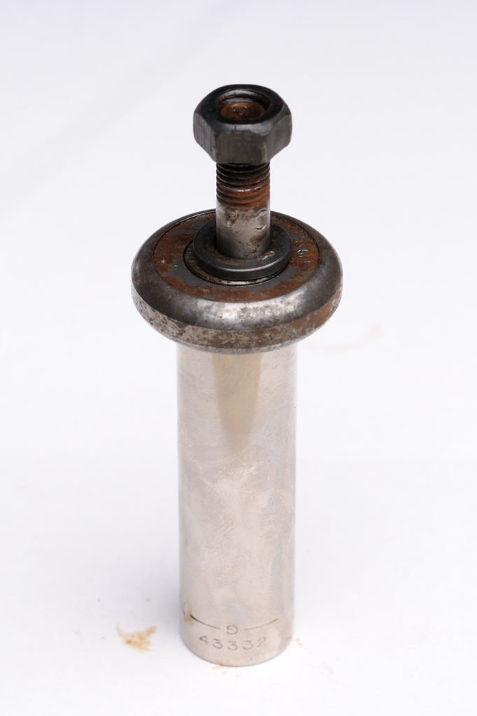
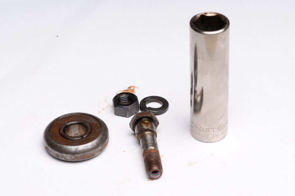
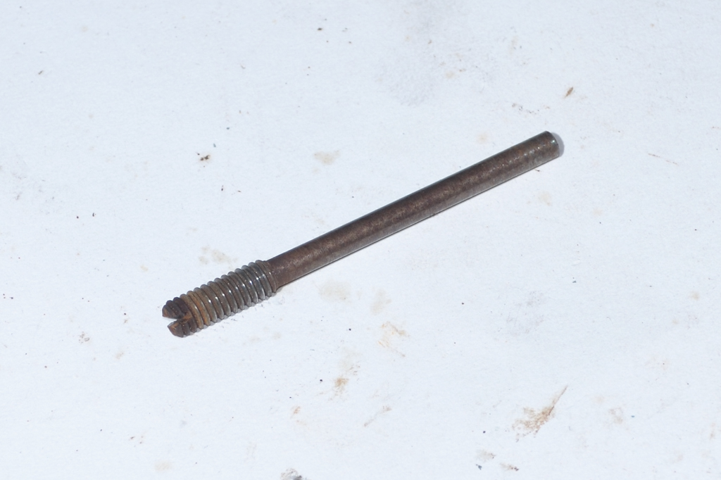
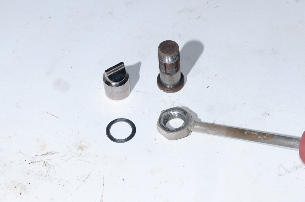
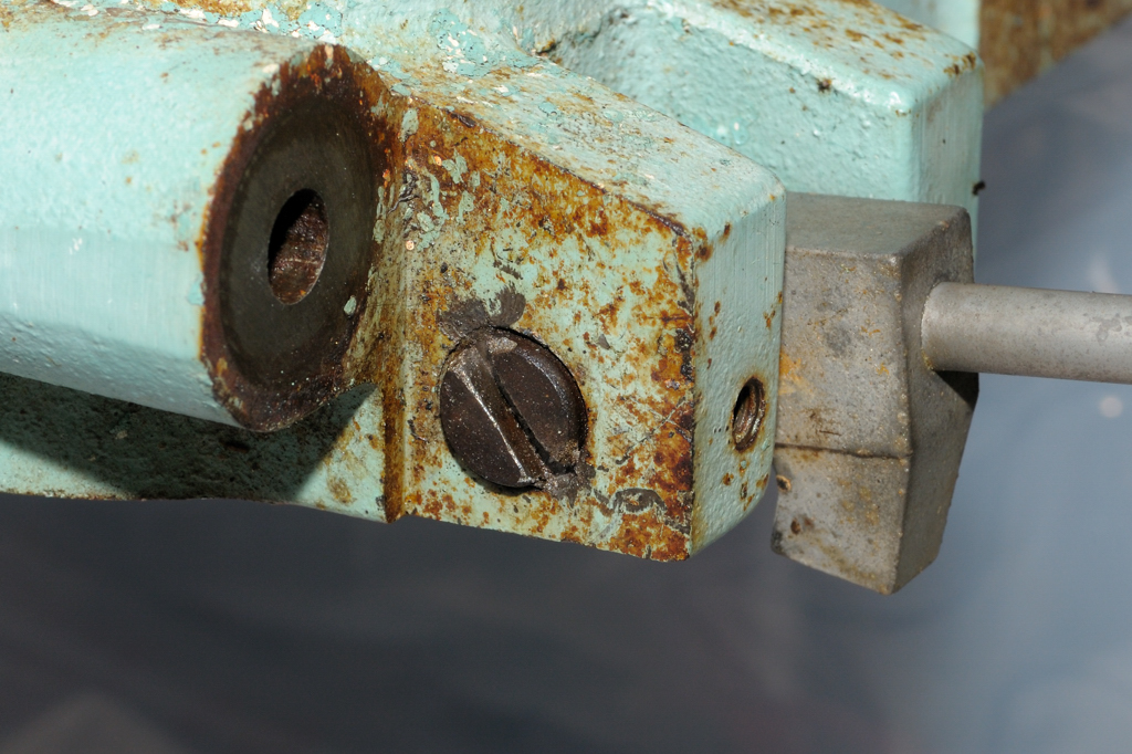
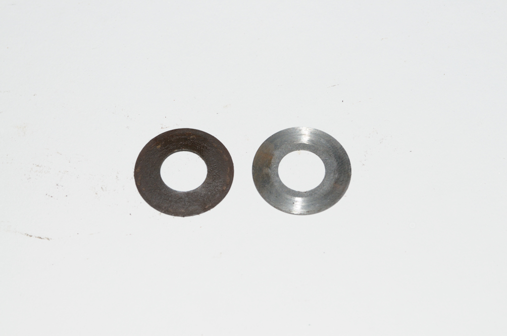
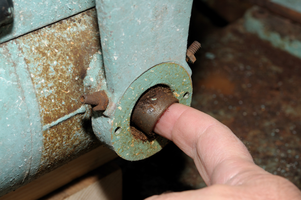
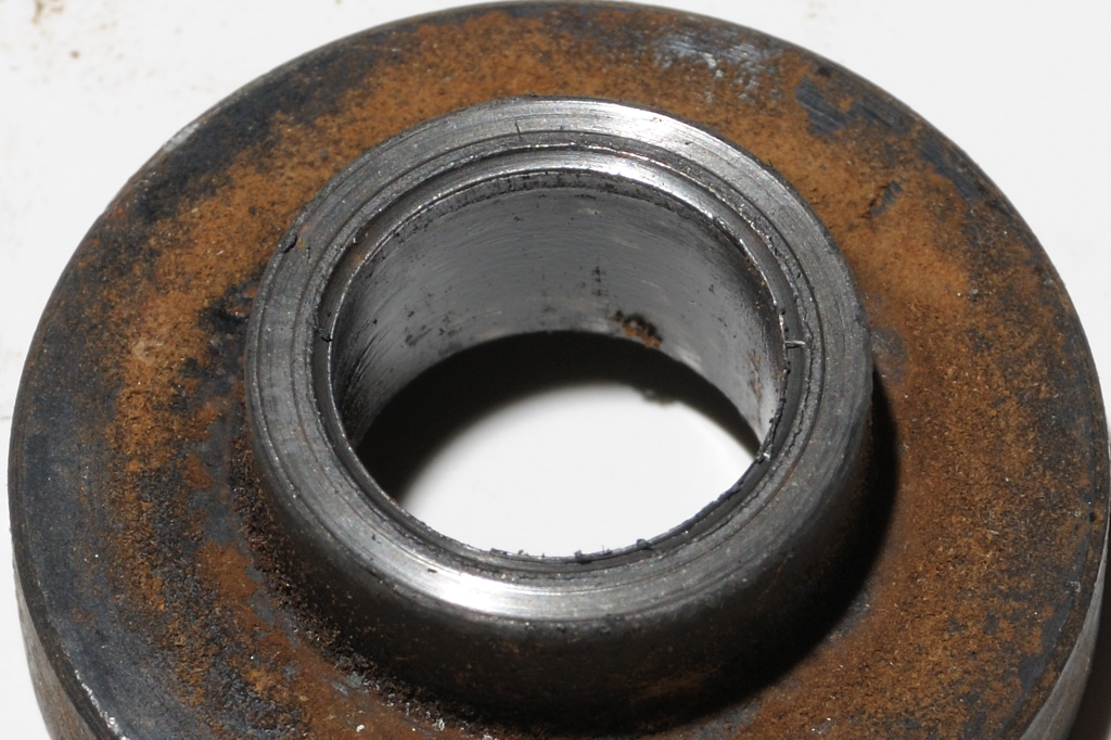
I applied a little pressure and off came the arbor spacer, albeit grudgingly. This should not be the case. Apparently it was bound against the bearing and some grinding had occurred at some point. There were very sharp shards around the edge of the spacer where it had melded with the bearing.

Take a look:


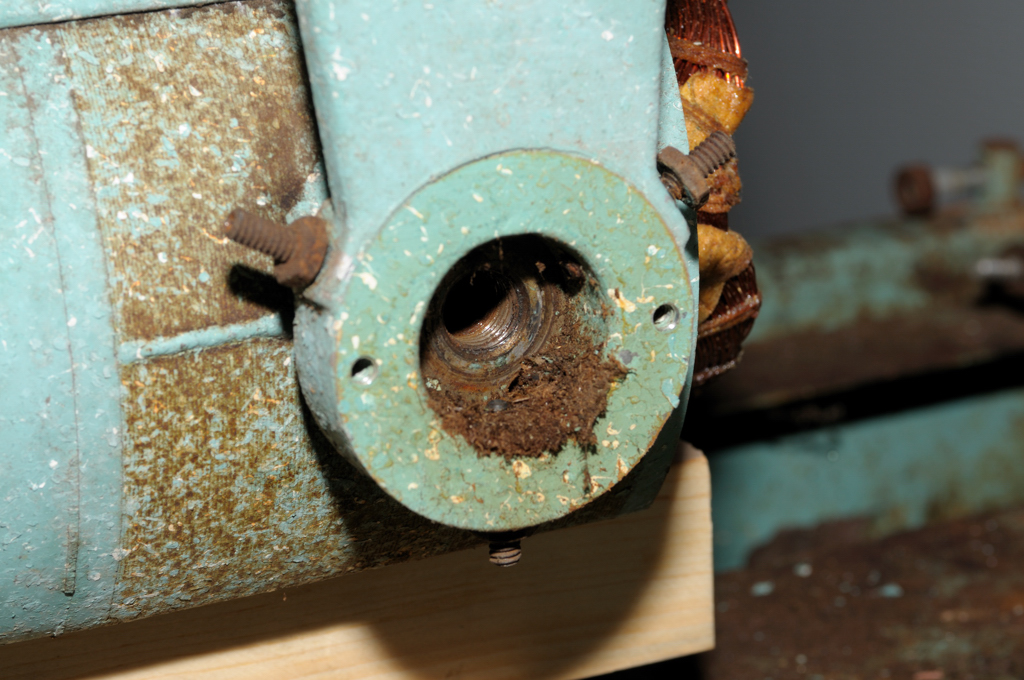
Not so good... I'll have to pay attention to why this might have happened later. That should just be a flat, happy surface. My suspicion is that the previous owner may have over-tightened the blade, smashing the spacer into the bearing, although this usually results in visible damage to the threads of the arbor.

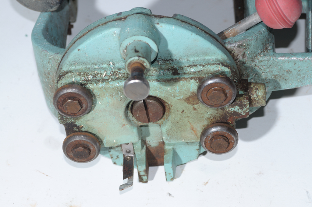
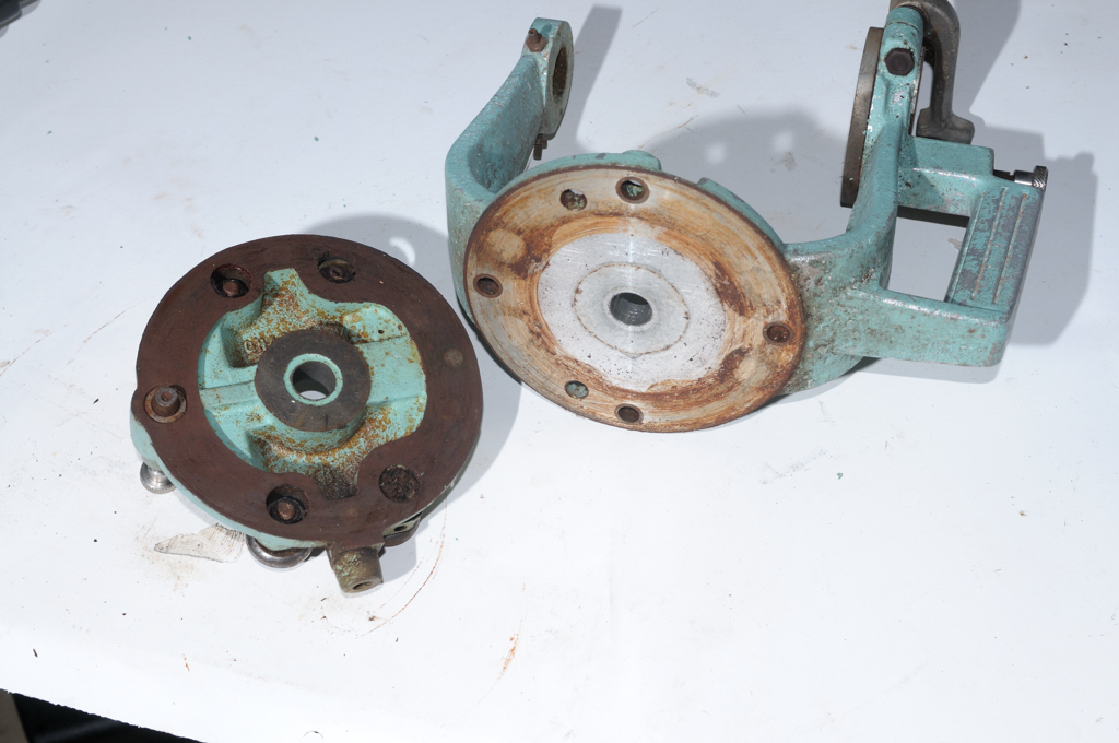
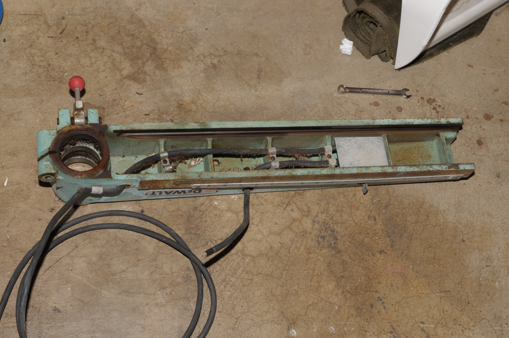
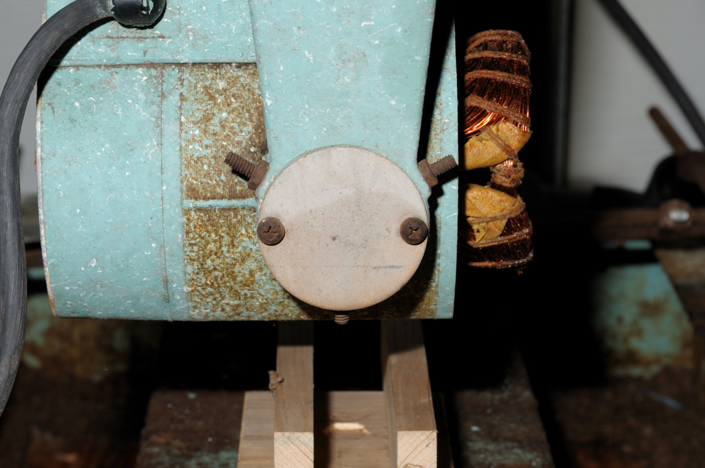
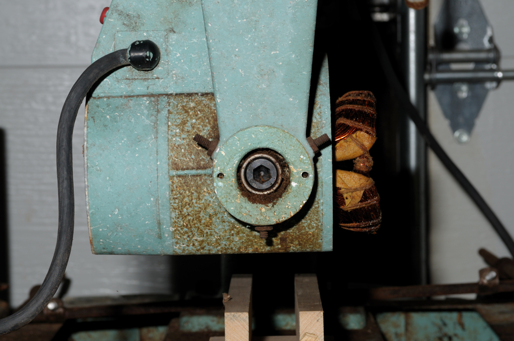
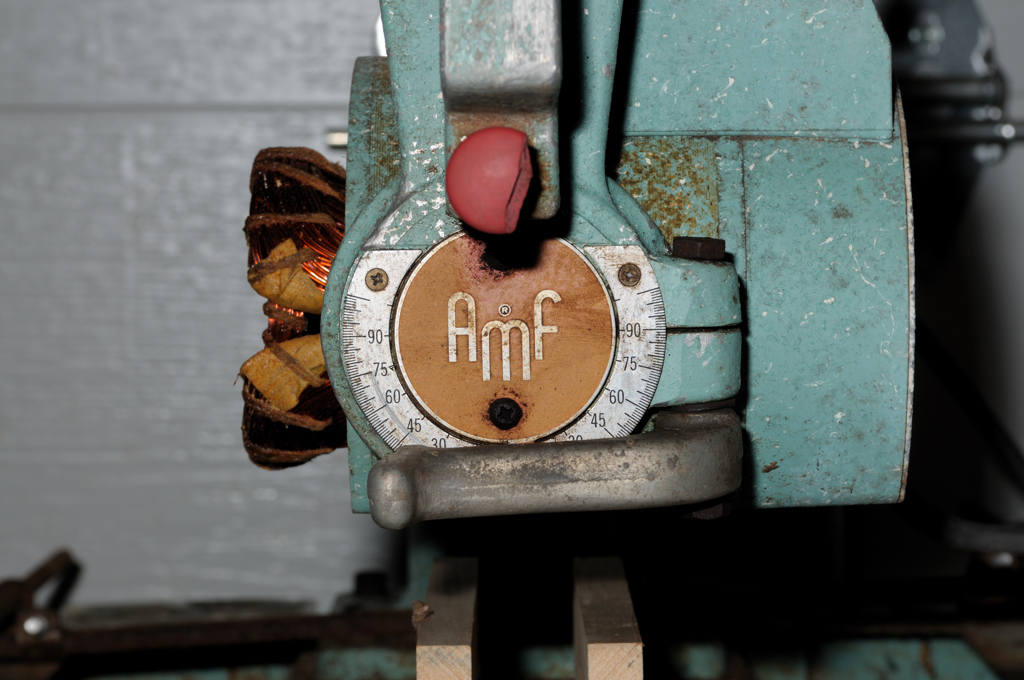
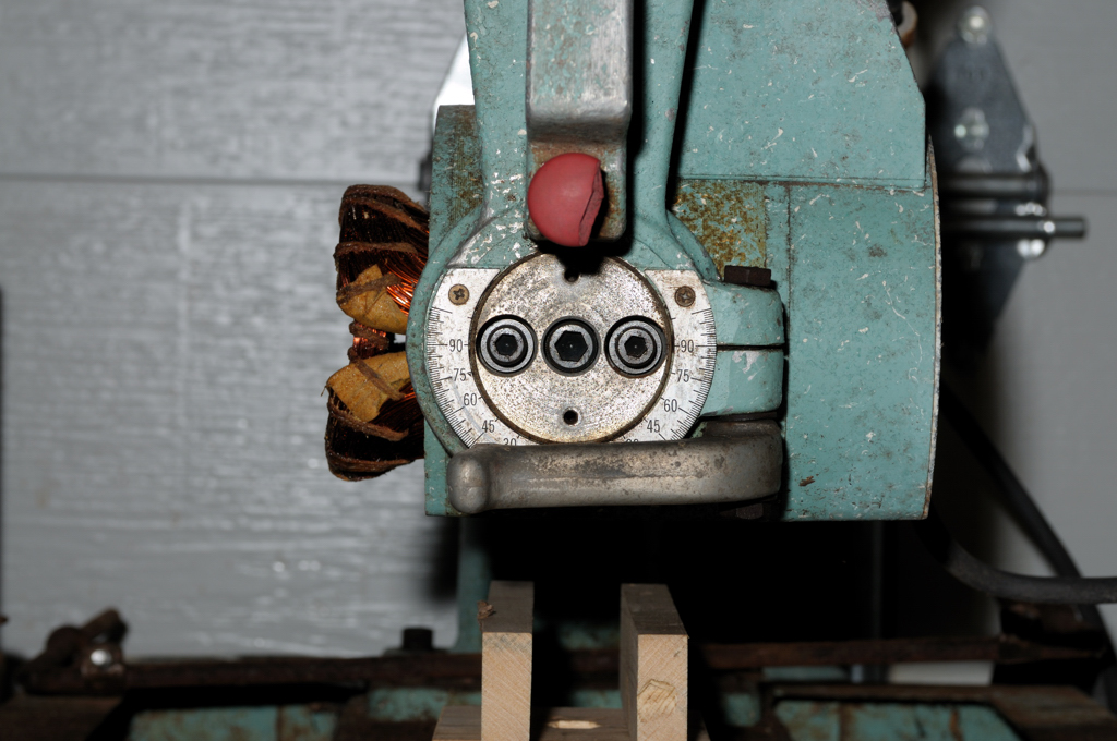
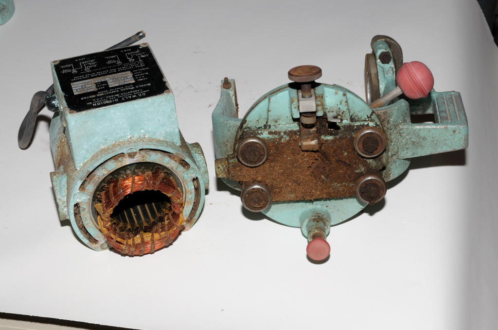
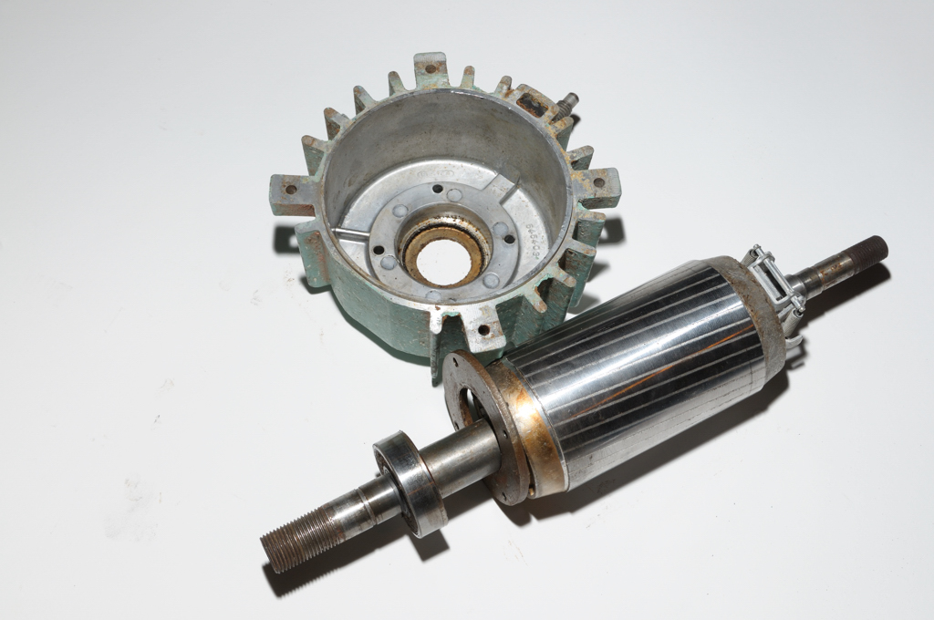
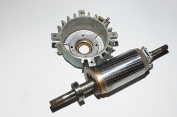
Step 15 - Separate the bell from the bearing and rotor. First reomve the screws holding the cover plate on the front of the bell. These screws hold a bearing retainer in place so once they are removed the bearing retainer will be loose in the motor. Turning it on now and you will likely destroy the windings.

Get yourself a hairdryer and heat the bell for 60 seconds. This will cause the metal to expand slightly. Then I simply used my hands to pull the housing off of the bearing.

It worked! The bell and rotor separated easily.

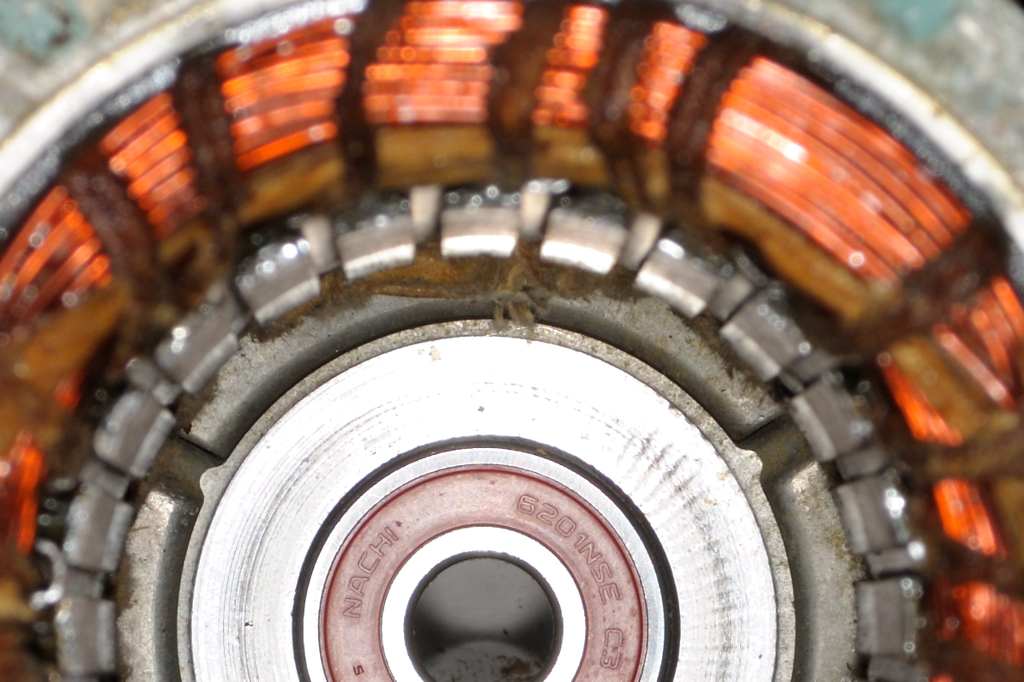
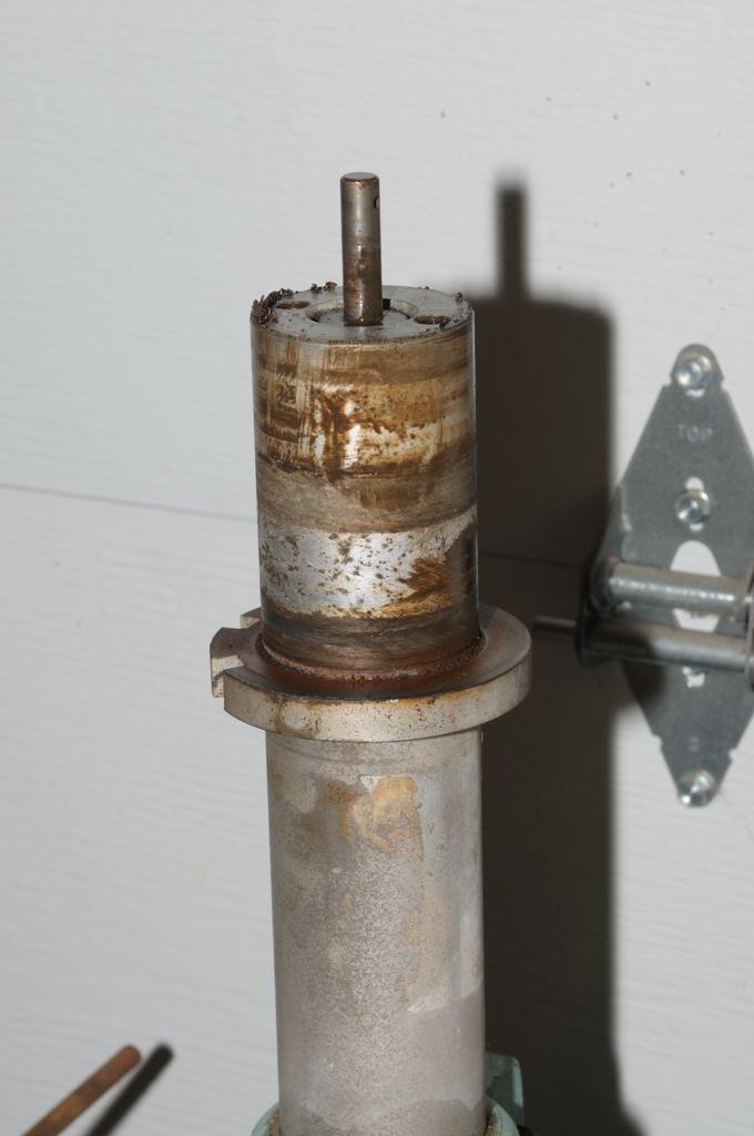
Here you can see the bearing retainer resting up against the rotor.


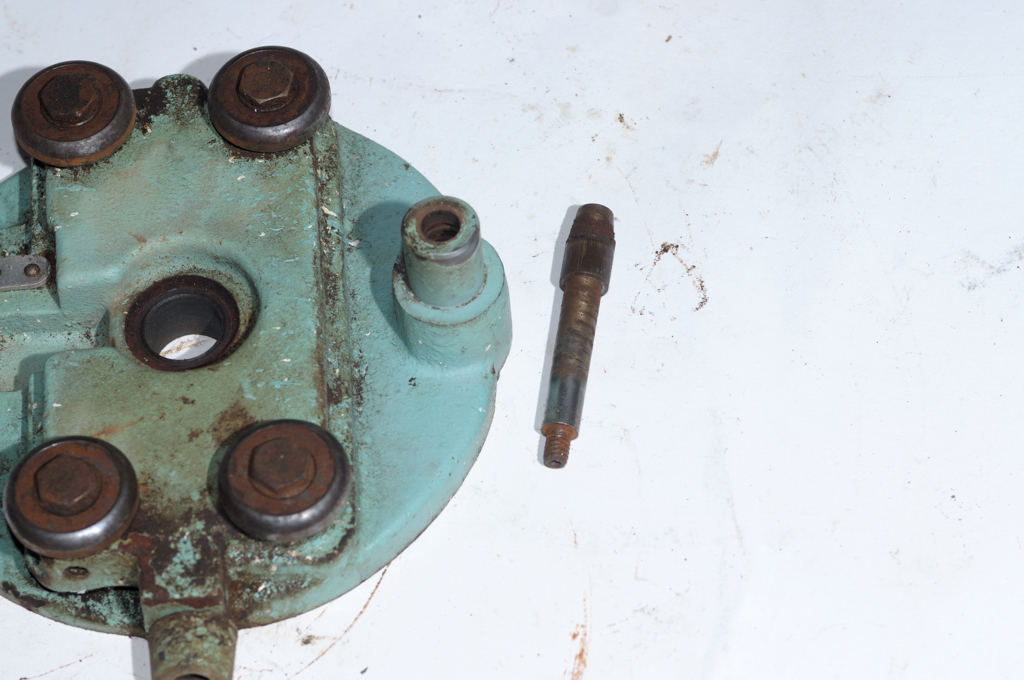
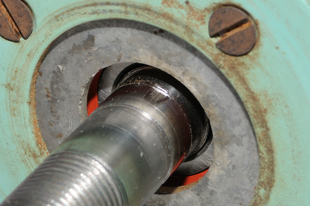
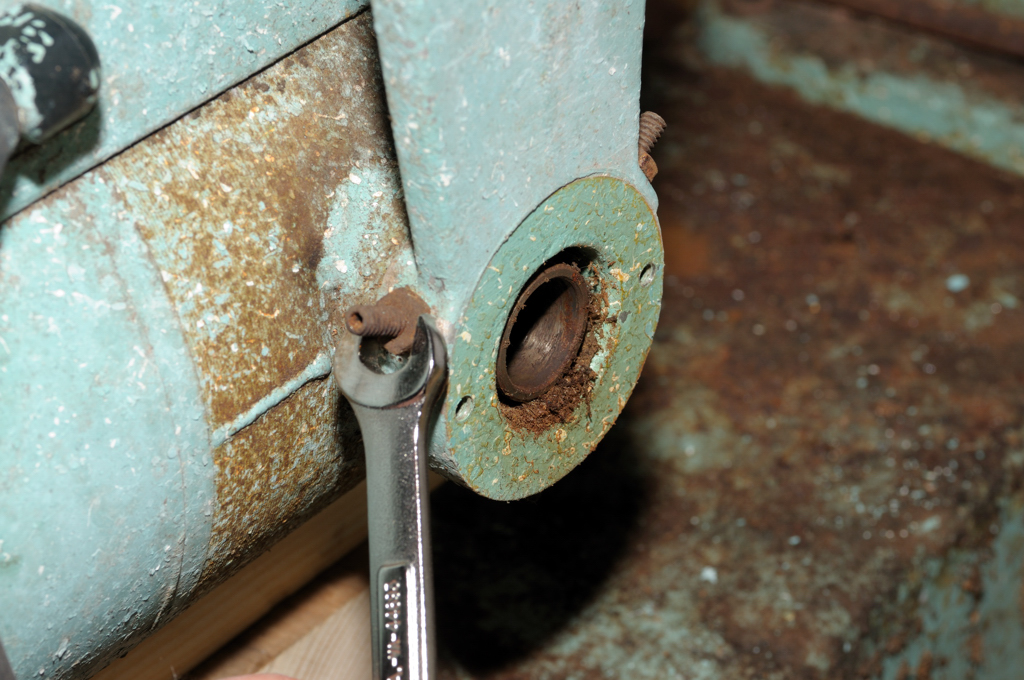
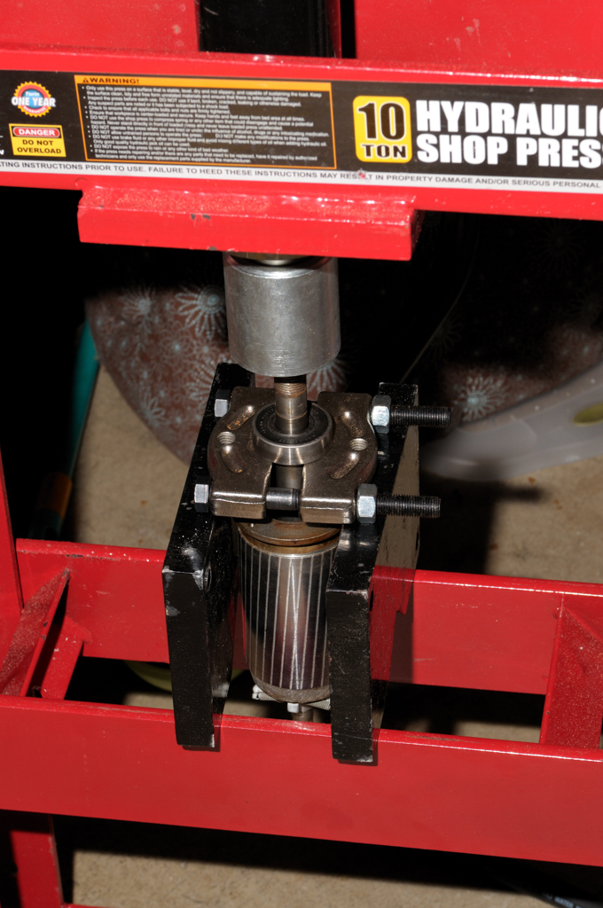
Step 16 - Next up is using a press to get the front bearing off of the shaft. First you have to remove the snap ring holding the bearing and shim washers in place (Photo Needed). Set those aside.

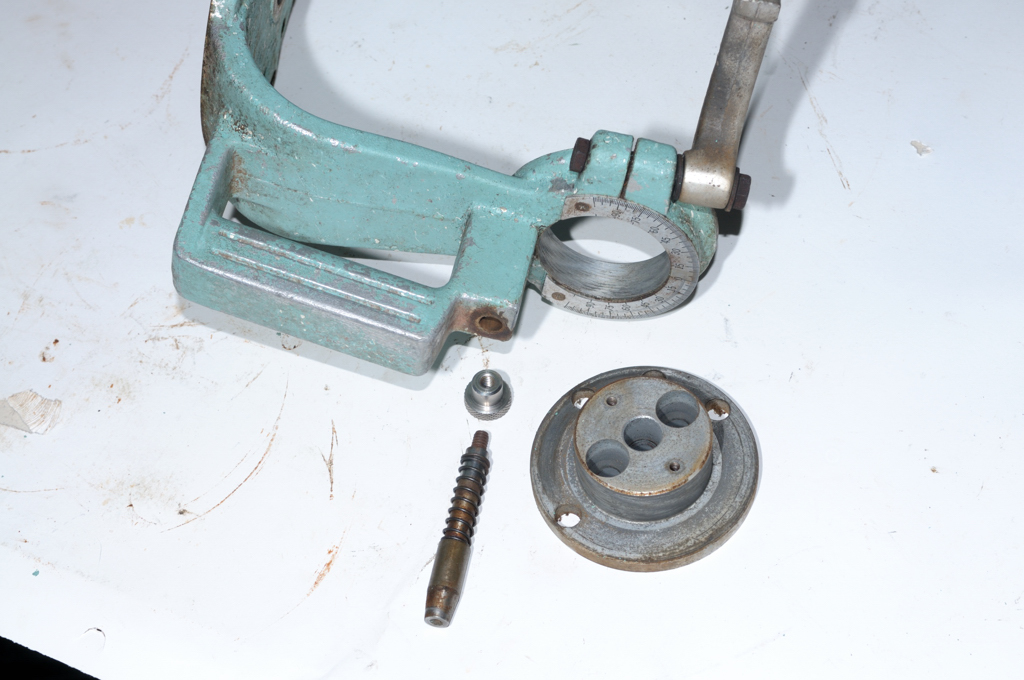
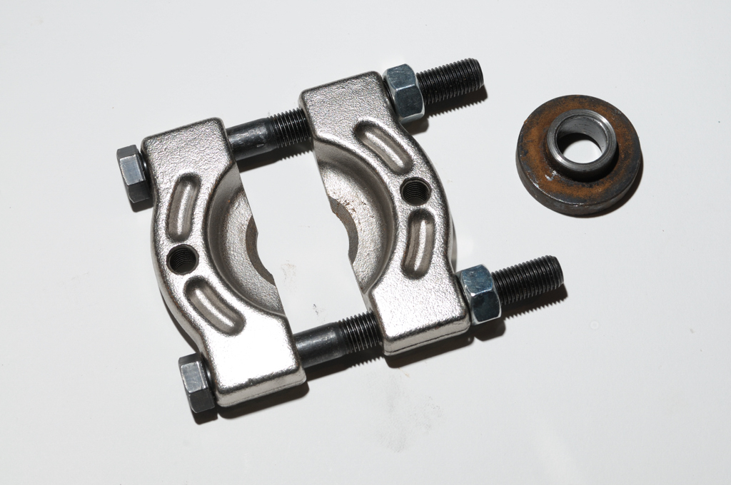
Once again I use the bearing splitter to get the flat end snug up against the races of the bearing (but not too snug or you will likely shave off a piece of the shaft). Then position the splitter against the two stands and lower the press onto the arbor. Give it a few pumps and off comes the bearing.


The bearing is a MRC 203SFZ. Accurate lists it as 6203-ZZ. I'll call tomorrow and order those as well as the 6201-ZZ from Day 2 and the 4 roller bearings you can see on the RAS Ways posting (They are Nachi 81004). I will post with the prices and then we'll go onto another set of topics while we wait for the bearings to arrive.

I spoke with Lynne at Accurate Bearing 1-800-323-6548 and ordered the following:
1 x 6203-LL @ $2.74 fan side bearing
1 x 6201-LL @ $3.16 arbor side bearing
4 x 81004 @ $8.00 carriage rollerhead bearings

$37.90 plus USPS and we're good to go for bearings for the 925.

The "LL" denotes a rubber seal while the "ZZ" denotes a metal seal. Originals are usually rubber and Lynne tells me that rubber is a better seal to keep out dust. Good enough for me.

The press is a Torin Big Red Hydraulic Shop Press with Gauge Dial — 10-Ton, Model# T51003 - $239.99 plus shipping from Northern Tool.


Would I buy it again? No. Why? It is too heavy for UPS to ship and not destroy in transit. It is not particularly well made. Does it do the job? Yes.

I would have preferred a large 1950's arbor press but I couldn't find one.

If you want a decent press "try to find one locally" would be my advice.

I won't go too far until I re-assemble the motor with the new bearings and confirm that we have a winner. A DeWalt RAS with an un-salvageable motor is a crime of nature but still a remote possibility. I'll cover some other tools and techniques in the next few days. At the very least we'll shine up some metal to have something pretty to look at.

Day 4